


What is a economizer and heat exchange tube designs?
What is a economizer?
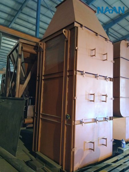
A economizer is essentially a tube-type heat exchanger used to heat water prior to entering a steam drum (circulating section) or a water wall (once-through section). economizers are also known as economizers stemming from the use of such economizers to reduce operating costs or fuel water heating by recovering additional energy from exhaust gases. economizers also reduce the likelihood of thermal shock and large temperature fluctuations when water enters a steam drum or water wall. Figure 1 illustrates the location of a economizer on a steam drum boiler. economizers are typically cooled by the last water before the air heater.
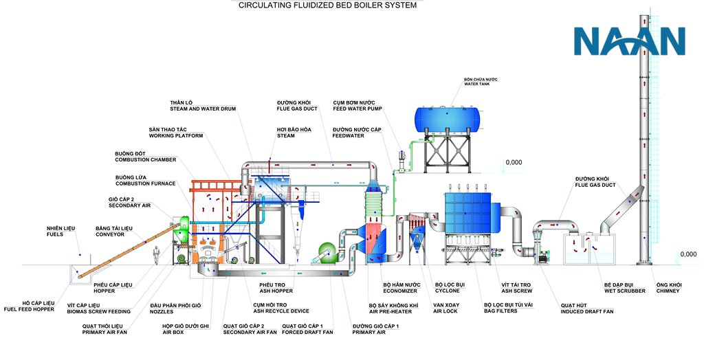
Figure 1: Position of economizer and air heater in a typical steam drum boiler
Types of economizer Surfaces
Smooth Tubes
The most common and reliable design of economizers is the smooth, continuous, crossflow tube type. (See Figure 2a.)
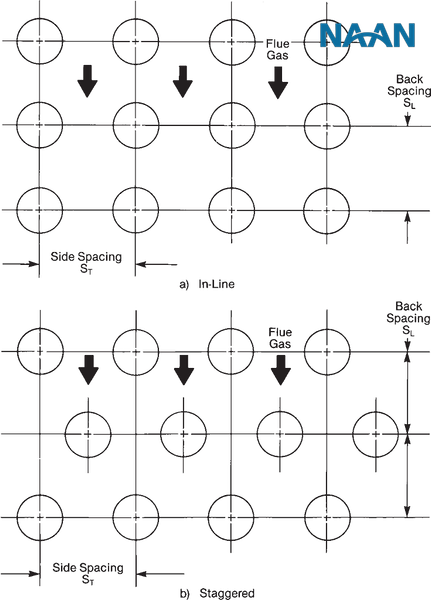
Figure 2: Tube arrangement in a economizer
When burning coal, fly ash creates a high fouling and erosion environment. Rows of straight tubes minimize the potential for erosion and ash accumulation compared to staggered arrangements as in Figure 2b. It is also the most aerodynamically clean geometry. However, these benefits must be weighed against the potentially higher volume and cost of this arrangement.
Extended Surfaces
To reduce capital costs, most boiler manufacturers have developed economizers with various types of heat transfer fins to enhance gas side heat transfer rates. Fins are a cost-effective means to reduce the size and overall cost of the economizer. However, surface cleanliness is a primary concern. In selective boilers, such as biomass-fired boilers, extended surface water heater equipment is not recommended due to specific fly ash properties.
Studded Tubes: Studded tubes perform well in gas-fired boilers. However, studded tube economizers may have higher gas side pressure drop than equivalent finned tube devices. Finned tubes perform poorly in biomass-fired boilers due to high erosion, heat transfer loss, increased pressure drop, and ash fouling.
Vertical Fins: Tubes with vertical fins arranged in staggered rows, as in Figure 3, also perform poorly over extended periods of operation. Excessive ash fouling and erosion in biomass-fired boilers have led to frequent replacement of these economizers. In oil and gas-fired boilers, cracks have occurred at the ends of the fins. These cracks have propagated into the tube walls and caused tube failures in some applications. Fly ash accumulation can also be an issue (limited space).
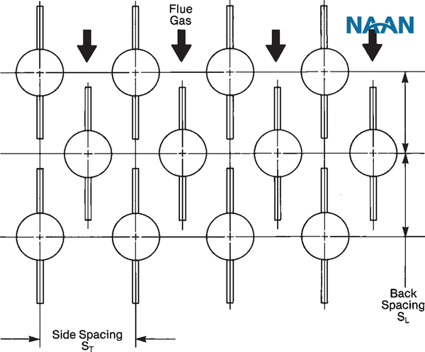
Figure 3: Vertical fins, staggered tube arrangement
Helical Fins: Tubes with helical fins (Figure 4) have been successfully applied to some biomass, oil, and gas-fired equipment. The fins can be closely spaced in cases where there is no fly ash or oil ash. Fin step (6.4 mm), fin thickness ranging from 1.5 to 1.9 mm, and fin height of 19.1 mm are typical. For tubes with an outer diameter of 51 mm, these fins provide ten times the effective surface area compared to smooth tubes over a unit length. When burning heavy oil or biomass, wider fin spacing must be used and proper measures taken to keep the heat transfer surface as clean as possible.
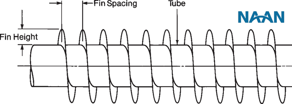
Figure 4: Helical fins
Rectangular Fins: Square or rectangular fins, arranged perpendicular to the tube axis on straight tubes as in Figure 5, are sometimes used in enhancements. Fin spacing typically varies between 13 and 25 mm, and fins are typically 3.18 mm thick. There is a longitudinal slot in the middle because two halves of the fin are welded to the two sides of the tube. Most designs are intended for gas velocities below 15.2 m/s. However, due to tight, deep spaces, fly ash accumulation is a hazard with such designs.
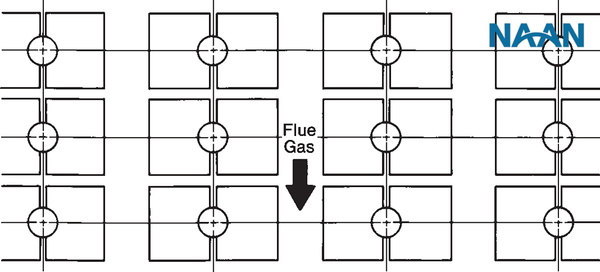
Figure 5: Rectangular fins, straight tube arrangement
Baffle Plates: Tube ends must be baffled completely (Figure 6) to minimize exhaust gas leakage around finned bundles. Such swirling flow can reduce heat transfer, create excessive shell temperatures, and biomass combustion may lead to tube erosion due to high gas velocities. Baffle plates are also used with smooth tube bundles but are not as critical as with finned tube bundles. Erosion at tube bend radii can be reduced by shielding the bends.